Equidistant Converter The Equidistant Converter is intended to make the equidistant correction in the flow program file. Input data are files of the flow program in the ISO-7bit language. Output data of the Converter are processed data in the text form of the flow program file, and also in the ISO-7bit format. Converter is the interpreter of ISO-7bit commands. It consists of two levels, one is platform-dependent and another is platform-independent. The platform means the concrete version of the control system with its own version of the ISO-7bit flow programs. The platform-independent level includes data and methods, which are common for all platforms: Transformation of data into the internal format. The prototype of the geometric processor. The prototype of the interpreter. The prototype of the flow program block. Auxiliary classes of common purposes.
The platform-dependent level realizes peculiarities of the concrete platform: The set of concrete G and M functions. The interpreter of the flow program. The mode of the flow program block. The model of output data presentation.
The platform-dependent and platform-independent levels cooperate tightly. On the platform-independent level there are mainly presented data and methods of their obtaining and saving. On the platform-dependent level there are described rules of data transformation and methods of receiving output formats of these data. 
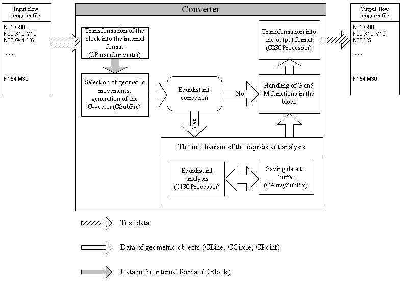
Pic.1. Scheme of work of the Equidistant Converter The block of the flow program comes to the Converter entry in the form of the text string. It is translated here into the internal format, and data are processed: The following work depends, whether the Converter is in the regime of the equidistant correction. If no, data will be immediately transmitted for generation into the output file. Otherwise, there will be started the mechanism of the equidistant correction. It means, that the flow program block will be put into the buffer and additionally processed (the analysis of intersection with other flow program blocks; correction of the geometric movement in the block). Then, there will be processed G functions and data will be transmitted for generation into the output file. Processing of the equidistant contour
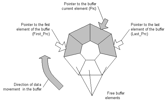
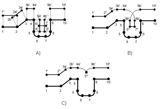
Pic. 2. The circular buffer In order to analyze the equidistant contour, it is additionally necessary to save information about previous contour elements. The circular buffer serves for this purpose. The number of elements defines the depth of the equidistant correction. The buffer works in accordance with the FIFO principle (First In First Out). The first step of the equidistant correction consists in calculating new parameters of geometric contour elements, taking into consideration the tool radius (see Pic. 3à). The next step is calculating the continuous contour (see Pic. 3b). The intersection points of neighbor elements must be found. For example, the point 2’’ in the Pic. 3b is the intersection of two lines, 1’2a’ and 2b’3a’ (see Pic. 3a). If intersection points are absent, the additional element will be generated. The arcs either 3a’3b’ or 4a’4b’ could be examples. After the calculation of the continuous contour, the block of the flow prograqm will be put into the equidistant buffer. 
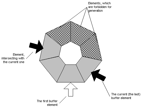
Pic. 3. Generation of the equidistant contour Afterwards, the buffer data will be processed and the final equidistant contour will be built. The intersection of the current block and other buffer blocks will be found. If exists, the geometry of corresponding elements will be corrected, and the generation of blocks between intersected blocks in the buffer will be forbidden (see Pic. 4). 
Pic. 4. The circular buffer For instance, circles 4a’4b’ and 9a’9b’ are intersected in the Pic. 4b. The contour, submitted in the Pic.3c, will be the result of correction.
|