Contour analyzer PurposeContour Analyzer is intended to evaluate and to transform afterwards the initial geometric part contour into another one, taking into consideration parameters of the cutting tool. The geometric part contour is submitted by the set of elementary sections, which are lines and curves. Input and output parametersThe program is started from the command line, while it is initialized with the help of input parameters. These parameters are defined after the name of the executable module and the blank. All parameters in square brackets are not obligatory, because they have default values. The description of input parameters is presented in the Table 1, while values of the output parameter are shown in the Table 2. ContourA.exe IN_file OUT_file [min_ANG] [max_ANG] [accuracy] | Parameter | Description | Default value | | IN_file | The name of the initial flow program file in ISO-7bit language | Absent | | OUT_file | The name of the output file in ISO-7bit language; this file describes the part contour after machining | Absent | | [min_ANG] | The minimal cutting angle of the tool | 45 | | [max_ANG] | The maximal cutting angle of the tool | 90 | | [accuracy] | The calculation precision, - the number of digits after the decimal point (10 as maximum) | 1
|
Table 1. The description of input parameters Value
| Description
| | Ok | The input file has been successfully machined; the output file with machined contour has been gotten. | | 0 | The input file has not been found or the output file cannot be created. | | 1 | The intersection of the left tool side with one of the line elements has not been found. | | 2 | The intersection of the right tool side with one of the line elements has not been found. | | 3 | The curve (G03) cannot be machined fully. The tool is located in the initial point. Machining could not be started from the initial point. | | 4 | The curve (G02) cannot be machined fully. The tool is located in the initial point. It is impossible to find the contact point between the circle and the tool. | | 5 | The curve (G02) cannot be machined fully. The tool is located in the initial point. It is impossible to find the line, connecting the contact point with one of the following contour section. | | 6 | The curve (G03) cannot be machined fully. The tool is located in the initial point of the circle. It is impossible to finish machining at the end point. | | 7 | The curve (G02) cannot be machined fully. The tool is located at the end point. It is impossible to find the contact point between the circle. | | 8 | The curve (G02) cannot be machined fully. | | 9 | The name of the output file has not been defined. | | 10 | Values of the minimal and maximal angles are the same. | | 11 | The defined precision does not correspond to requirements (it is either less than 0 or more than 10) | | 12 | The radius in the flow program is less than 0 or equal to it. | | 13 | The error in the text of the flow program: the value or the precision are too big; the precision of the axis or the parameter is too big. | | 14 | Errors in the text of the flow program of the input file. |
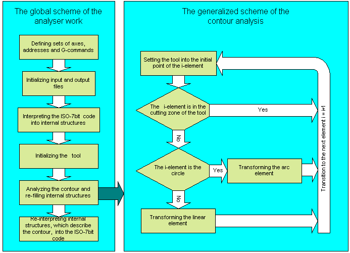
Table 2. Values of the output parameter The algorithm of computationThe global scheme of the computation algorithm is shown in the Pic. 1. 
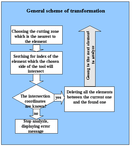
Pic. 1 The global scheme of computation Definitions of axes, addresses and G-commands are necessary to identify components, which are responsible for recognition of the ISO-7bit language. After initialization of the recognition components, there will be opened both the initial file for reading and the output file for recording. At the next step, the code of the initial file of the flow program will be translated into internal structures of the Contour Analyzer. If the contour is ready for analysis, the tool will be initialized. The next step is the main one. It makes analysis and refilling of internal structures of the Contour Analyzer. When the analysis is finished, descriptions of the contour elements, which are structures of the analyzer, will be translated into codes of the flow program in the ISO-7bit language. The contour is analyzed in the following way. The tool is removed into the initial point of the first contour element. Then the condition is checked, whether the element is referenced to the tool-cutting zone. If yes, the next element is taken from the set and the tool is positioned in the initial point of this element. If no, the type of the element is analyzed (the line or circle), and the contour is transformed, depending upon the type. It is necessary to point out, that transformation for lines and circles is substantially different. The difference is, that the check for the line is carried out for one parameter, the inclination angle; while for the circle it is made for two parameters, the tangent inclination angles in the start and end points of the element. The transformation of contour elements The general scheme of transformation is submitted in the Pic.2. If the element is not referenced to the tool cutting zone, there will be searched an element, with which the chosen side of the tool will intersect. As a result, the index of the element and intersection coordinates will become known. The program will be urgently stopped with an error message, if the intersection point and the element index are not found. 
Pic. 2. Transformation of the contour If the intersection point is found and the element index is defined, then, all elements between the current one and the found one will be deleted; and parameters of the current element will be corrected, taking coordinates of the intersection point into consideration.
|