|
|
New Approaches to Building NC Systems for Intelligent Control Department of Computer-architecture Control Systems, Moscow State University of Technology «STANKIN»
Vladimir L. Sosonkin, Georgi M. Martinov AbstractThe course of events in AI (Artificial Intelligence) is rather well known. There are attempts to use AI-elements in numerical control systems. Nevertheless, these attempts do not define the direction of efforts now, at the time when numerical control systems of a new generation are being developed. The main goal is to make control system an inexpensive, convenient, effective and reliable tool in the industrial environment. Thus, the conception of modern intelligent control systems has its unique features, connected with the latest computer technology. Among the unique features of the Intelligent Control Systems are their configurability and open architecture, the ability of their man-machine interface (MMI) to satisfy users’ requirements, the effectiveness and convenience of their operators work. Besides, they deliver exhaustive information about themselves and their objectives. All Intelligent Control Systems belong to PCNC type. Two approaches exist to select their architecture, the two-computer and the one-computer version. Both include PC-and NC-subsystems, and both have three-layer structures. The bottom layer consists of the computer- and the PLC-hardware, that represent the input-output controllers. The second level includes the operation and communication systems, while the top layer, the application. Either version of the Intelligent Control Systems requires object-oriented approach. The basic application components are represented by "control tasks", which include terminal, geometric, logical, technological, and dispatcher tasks. Each task is a module with some standard API-interface. The object-oriented channel is the only global communication facility for control tasks and modules. Its components fulfill services, such as delivery of the information by means of transactions, control processes, dialogue and configuration. They also execute miscellaneous functions and work with different data types. Configurability allows to adjust the system to any ISO-7bit (DIN 66025) language, to use customer versions of operator’s dialogue and screen structure, and to include any commercial program modules into the MMI shell. MMI plays an important role in intelligent PCNCs, serving as a means of revealing their functionality. A PCNC user would like to have an MMI, most convenient for his individual dialogue regiment and information contents of the screen. Therefore, MMI should be flexible and configurable; it needs to allow dialogue corrections or redefinition. MMI development includes complicated tasks, such as dialogue implementation and interpretation. SynopsisContours of the next NS-systems’ generation are not quite well defined now. Nevertheless, it is clear, that these systems will be fully oriented to the customer (or end user); even if the order of the customer will consist of one NC thing. Such situation makes it necessary to over-comprehend the whole architectural NC concept, both at the level of the system platform and at the level of applications. Though difficult it might seem to NC OEMs, they should refuse from traditional and successive decisions and drastically re-develop their software. It would be good to use new NC-system decomposition principles at that; to use the object-oriented approach (we mean MS Visual C++); to use new MS-technologies (OLE, COM); to use existing and original CASE-systems. Architectural concept The choice of the architecture of the PCNC-type numerical control systems may favor either two-computer or one-computer versions. The former has exceptionally high computing power and may be recommended for use in the following cases: Sophisticated multi-axial numerical control systems; PCNCs employing expanded embedded commercial application-CAM-tools, intended to automatically prepare and simulate by means of solid graphics the flow programs; PCNCs oriented on machine free-form surfaces; PCNCs applying complicated interpolation algorithms; PCNCs working at very high feedrates.
The one-computer version attracts the users with its low cost and the possibility to use standard computer hardware to the maximal extent. The advantages of this version prevail when powerful microprocessors, internal one-board PLCs, and intelligent input-output controllers are being used. In any architectural version of modern PCNCs, only the object-oriented approach is possible in the development of multi-megabyte PCNC software. It allows software to be well structured, well observable and highly reliable (Wright, 1994), (Sosonkin, 1998). Both the two-computer and the one-computer architectural versions are shown on Fig.1, where virtual two-computer and one-computer machines (i.e. vertical cross-sections of the architectural realizations) are compared. The two-computer system consists of PC- and NC-modules. Its both computers are organized as three-layered structures. The bottom layer comprises the computer hardware, PLC hardware, and the input-output controllers. The operating and the communication systems occupy the second layer. The communication system is elaborated as a virtual bus, and it can include TCP/IP protocols. The PC-module operating system is Windows NT. The NC-module should use a real-time operating system, for instance, from the UNIX family (Sadre, 1997). The relations between the PC- and NC-subsystems clearly reflect client-server connections. 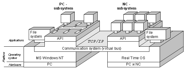
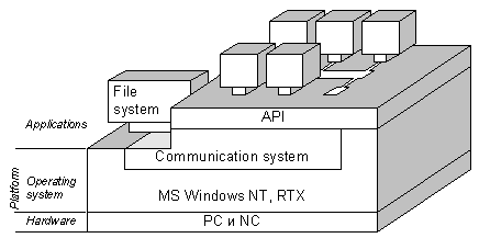
Fig.1. The two possibilities in the development of PCNC system
The one-computer system has the same set of application programs. The main operating system is Windows NT. However, at the this level ( i.e. the level of operating system) a real-time extension is needed (Dinges, 1995), (Labs, 1998). Another possibility is to use VxWorks or another operating system (Cleaveland, 1997). At the application layer, PC- and NC-subsystems preserve their function in the client-server interactions. A Notion About Control TasksControl tasks are the basic structural elements of the two-computer system. Among them, there are terminal, geometric, logical technological, and dispatcher tasks (Fig.2). The terminal task belongs to the PC-subsystem, while others, to the NC-subsystem. Each task, in turn, has modular structure with standard interfaces; these interfaces are oriented to send (Data) and receive (Data Request) data upon request. The object-oriented channel is the sole, global communication facility for control tasks and modules. It carries out server functions for the terminal task and its modules. It represents the server or the client in different situations for other tasks and modules. Objects of the object-oriented channel fulfill different services to deliver information to the terminal task and support the interaction between all other modules of the numerical control system. 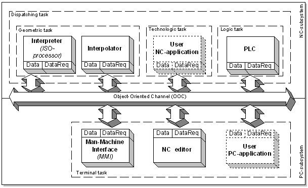
Fig.2. PCNC modular structure with common channel
The terminal task is submitted by two basic modules, the MMI and the NC editor (flow program editor). Various commercially available application systems can be included into the terminal task. The geometric task is the core of the NC-subsystem. It executes all geometric calculations, which are necessary for server drives in order to relatively feed cutter tools along the assumed part-contours with defined feedrates and precision. The geometric task includes two modules: the interpreter and the interpolator. The former executes the following functions: interprets flow programs; supports the actual value of the G-vector; separates streams of geometrical and logical instructions; carries out equidistant corrections and movement corrections in flow program blocks; adds artificial blocks for connecting equidistant contours; calculates IPD-codes (Interpolator Data) for the interpolator.
The interpolator executes feedforward and interpolation calculations and is able to use several concurrent interpolation algorithms in any flow program block. The logic task corresponds to PLC functions. Such PLC could be realized by means of either software or hardware. The hardware-realized PLC may be either external or one-board internal. The internal PLC may be oriented for either direct or distributed control (Otto, 1996). The technological task provides the on-line control of cutting-process parameters (for instance, for laser machining) or adaptive control of cutting in accordance with certain criteria of optimizing. The dispatcher task coordinates all other control tasks at the application level. Interaction of all modules of a one-computer PCNC system is supported by application interface (API) that plays the role of a virtual bus. All requests for information (Application Function Calls) are addressed only to API, while API functions supply the delivery of necessary information. For users, PCNC functionality and attractiveness depends mainly on API-functions filling. Most commonly, modern PCNC systems use digital autonomous feed servo-drives with SERCOS interfaces that are net controllers. The optic-fiber ring net of autonomous digital servo-drives might include eight or more coordinate axes. For instance, every millisecond each coordinate axis drive receives values of the absolute coordinate, feedrate and constraints for the asynchronous motor torque; the same coordinate drive in the same time period sends actual values of the absolute coordinate, feedrate, and motor torque. PLC input-output system is designed as an intelligent controller supporting net InterBus protocols for distributed control of cyclic logic. Real-time manager carries out the functions of the dispatcher task, coordinating other application modules. Object-oriented channelA series of features are unique for the one-computer architecture. One of them is the object-oriented realization of well-structured modules accomplished as "embedded objects" that request services from and suggest tasks to other modules. Another singularity is the object-oriented channel that works as a global server (Martinov, 1997). The object-oriented channel is the object cover over API functions. Yet another innovation is the development of an interpreter such as a software-hardware ISO-processor executing commands of the ISO-7bit language, as though these commands were machine instructions (Sosonkin,1994). The ISO-processor is able, for instance, to calculate spline coefficients in real time for every sequential four points of the part contour. As a whole, this version could be an example of the open architecture with configurable modules, according to the customer requirements. Configurability means setting up the system for any version of the ISO-7bit language, using the customer version of the operator dialogue and the screen structure and including, if necessary, commercial program modules into the MMI shell. The object-oriented channel (Fig.3) supports four groups of functions, which are intended: to deliver diverse information with the help of various transactions (Function of Requesting Data); to control processes, dialogue and configuration (Control Functions); to execute miscellaneous functions (Auxiliary Functions); to work with various types of data (Types of Data).
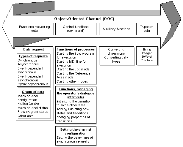
Fig.3. OOC interface
Data to be delivered belong to one of the following groups: machine-tool configuration, motion control, machine tool and NC system status, flow program status, other data. Each group requires data delivery with the help of various type transactions (sessions). There may be several types of transactions: synchronous, asynchronous, event-dependent synchronous, event-dependent asynchronous, cyclic asynchronous. For example, cyclic asynchronous transaction would be optimal for motion control. Transactions create a very economical mechanism, supporting the interaction of application modules. Control functions of the object-oriented channel are rather diverse. The term control of processes indicates a series of actions, intended to start a flow program or a manual-data-input line for execution, begin the reference point mode or the jog mode, and so forth. Corresponding objects of the object-oriented channel support all these functions. An important part of the control functions is devoted to the support and interpretation of the operator dialogue: they act to initiate transitions to other dialogue states, include new dialogue states and transitions, change properties of dialogue transitions, etc. Other elements of the control functions are responsible for the channel configuration. Auxiliary tasks of the object-oriented channel include converting data measures and types. The client requests information of desired types and measurements, supplied by the information source. Such a possibility is supported by corresponding mechanisms of the object-oriented channel. Furthermore, the object-oriented channel handles different data types, this property being supported by corresponding objects of the object-oriented channel. Client-server interactionsDuring client-server interactions, various situations may occur: the client may submit commands or generate requests to the server. In the former case, these commands do not need a reply; the latter case, however, requires a response, and transactions need be initiated (Fig.4). 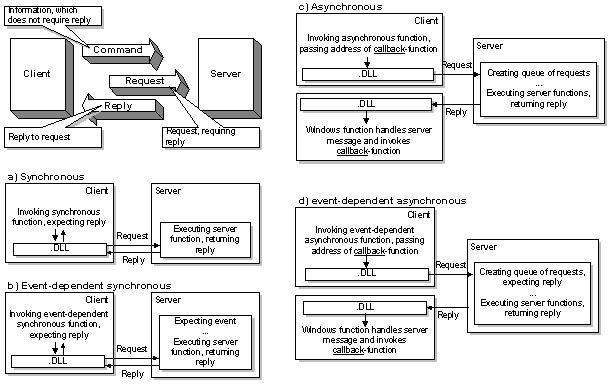
Fig.4. Client-server interactions
In the case of a synchronous transaction, client invokes the synchronous function in the DLL library, which, in turn, formulates a request to the server; the client suspends its work and expects a reply from the server during a certain period of time, no longer than a previously set "time-out". A timely reply initiates resumption of the client’s work. A poorly timed reply generates an error. During an event-dependent synchronous transaction, the client invokes the corresponding function in the DLL library, which formulates a request to the server; the client suspends its work and expects an answer from the server. After a certain definite event, the server sends a reply, which allows proceeding with the client’s work. If an asynchronous transaction is taking place, the client invokes the corresponding function in the DLL library and sends it an address of a callback-function; the library formulates a request to the server, and this request enters a queue of requests; the client’s work continues uninterrupted. The server function, when executed, returns a reply to the DLL library, which, in turn, invokes the callback-function, processing the reply. The callback-function could initiate the next asynchronous transaction; thus, there forms a cyclic asynchronous transaction. In the case of an event-dependent asynchronous transaction, the client invokes the corresponding function in the DLL library and passes to it the address of the callback-function; the library formulates a request to the server, and this request enters a queue of requests; the client does not stop its work. After some definite event occurs, the server sends a reply to the DLL library. This brings about the callback-function, processing the reply. Man-Machine Interface and Operator DialogueThe man-machine interface, MMI, within the terminal task plays a very important role in modern PCNCs. The whole functionality of the control system reveals itself through MMI. Today, PCNC user is interested in an MMI that satisfies his need for dialogue and contents of the information appearing on the screen. In this regard, MMI needs to be flexible and configurable; it must be able to admit not only correction of the dialogue, but its full redefinition (Solomencev, 1997). The virtual structure of the terminal control task is shown on Fig.5. MMI itself and the software tool for automatic preparing and verifying flow programs, as well as NC editor, are situated at the application (top) level. Below, there is a layer filled with classes of objects of the object-oriented channel. These classes cover both the standard library MFC (Microsoft Foundation Classes) and the application interface API. The interface Win32 API is basic for applications in the environment of Windows NT. The layer NC drivers is a problem-oriented extension of the operating system at the level of devices (i.e. special NC system controllers) under real-time control. The hardware layer is at the bottom of the virtual structure. 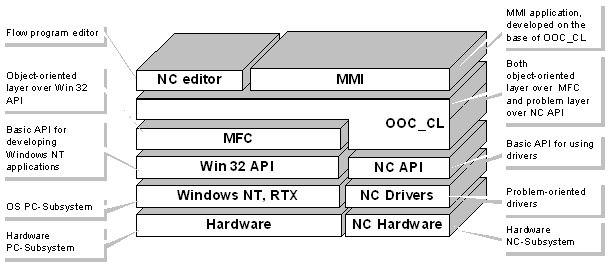
Fig.5. Virtual structure of MMI - application
Classes of the object-oriented channel are also organized in layers: basic classes, the layer of reflection, the layer of application, as indicated on Fig.6. 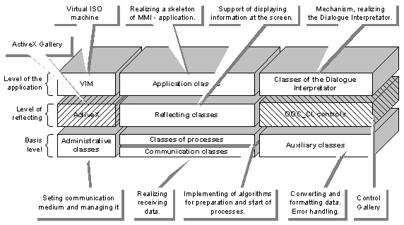
Fig.6. Virtual structure of OOC_CL
Administrative basic classes are intended to set up and control the communication environment. Communicative basic classes function to organize acceptance of information. Basic classes of processes realize algorithms, preparing and starting the work of processes in the system. Basic auxiliary classes work on converting and formatting data and handling errors. The layer of reflection includes reflective classes responsible for the output of information on the screen. There also exist two galleries: the gallery of control elements OOC_CL and the gallery of ActiveX control elements. Control elements are intended to visualize information on the screen. ActiveX elements submit themselves to be an application extension of the OLE-library; they possess powerful setup mechanisms (colors, fonts, borders, etc.). The layer of application consists of three groups of classes: application classes, creating the skeleton of the MMI application; classes, supporting the work of the ISO-processor; classes, supporting the work of the interpreter of the operator dialogue. The typical structure of the MMI application frame window includes the following features: the window header (option), the menu (option), the never-covered window of the control system status (StatusBar), the application work window, the functional key-line (ToolBar), the application status (option) (Fig.7). The StatusBar and the work window are filled with control elements; same control elements could be present in both windows. 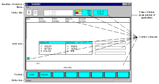
Fig.7. Structure of the MMI-application window
There are different types of control elements, including usual types, not connected with information to be received from the NC-subsystem and general-purpose control elements. Usual control elements visualize, for instance, the system information, headers, and so on. General-purpose control elements visualize digits, letters and marks, G-vector, icons of current modes, mixed information, coming from several communicative objects (for instance, percentage relation of given and real feedrates), etc. The gallery of control elements can be expanded by the customer. Implementation of the operator dialogue (in accordance with customer requirements) and interpretation of the dialogue are complicated tasks arising during MMI development. In the process of interpretation, screens and ToolBar-functional-key names are changed, commands and requests are transmitted into the NC-subsystem, operator actions are monitored. During the process of development, such important notions as the State and Transition may be juxtaposed (Fig.8). The State is a stable situation in the control system after each elementary operator action (such as pushing the ToolBar button). The Transition means a change of States as a result of elementary actions. The most important events in the control system are initiated by operator during the dialogue with the system, i.e. as a result of Transitions. Some events in the control system depend on being staying in various States. 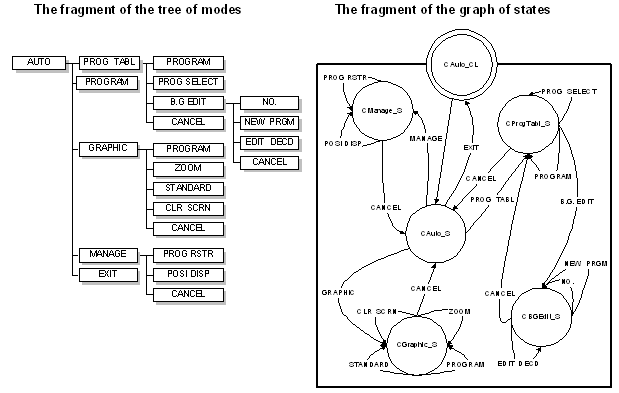
Fig.8. Interpreting the operator’s dialogue
The customer requirements concerning the contents and structure of the dialogue could be submitted by means of the dialogue tree. However, the tree is a unidirectional structure that is unable to show returns to the earlier stages of the dialogue. That is why, the graph of states could be a more convenient and precise model of the dialogue. For such a graph, an additional notion about the Complex State is introduced. The Complex State, in turn, could be launched as a whole graph. The notion about Complex States makes easier the development of sophisticated graphs. This procedure could be made automatic and result in generation of interpreter source codes. The development of MMI follows certain sequential stages. Formal models of the development process make it possible to create any application interfaces in accordance with customer requirements. MMI is a shell, and ready-made commercial or specially developed application systems could be included into it. One of them is a special software tool system NC editor, which is intended to implement, edit and verify flow programs. The main part of the screen is occupied by three windows: the window of parameters, the window of the text editor, and the window of the graphic presentation. The window of parameters could be used to enter one block or parameters of the standard cycle. The window of the graphic presentation illustrates either the current G-function or the structure of the standard cycle. It could also be used for graphical simulation. The text editor has special algorithms to work with very long flow program files (as long as tens of megabytes, for example). The software tool could be adjusted for any version of the ISO-7bit language with the help of the configuration file. ConclusionThe modern PC techniques substantially exempted NC-systems’ developers from any troubles, connected with implementing hardware of control systems. But there have appeared quite new problems for NC OEMs: to use the PC platform the most effectively and to build the architecture, which is really open. It would be a mistake to consider, that international projects , like OSACA, have decided the whole number of questions, referring to the development of the next generation of NC systems. Our opinion is that additional discussions are necessary.
ReferencesCleaveland, P. and Labs, W. 1997. «Windows NT for real-time control: Which way to go?». I&CS, January:1-8. Dinges, C., Krause, K. and Langhammer, D. 1995. New Solution for Machine Tool Controls. Engineering & Automation, 3-4: 4-7. Labs, W. 1998. «MS Windows: In control?». I&CS, July: 48-56, 59. Martinov, G.M. 1997. Open NC system based on common channel. Avtomobilnaya promushlennost, 4:31-34. Otto, H.-P. and Rath, G. 1996. State diagrams. A new programming method for Programmable Logic Controllers. Software Engineering for Manufacturing Systems: Methods and CASE tools. Edited by A.Storr and D.Jarvis. London: Chapman&Hall, pp. 27-37. Pritschow, G., Spur, G. and Weck, M. 1996. Komponenten und Schnittstellen fur offene Steuerungssysteme. Munchen, Wien: Hanser, s.216. Rembold, U., Nnaji, B.O. and Storr, A. 1993. Computer Integrated Manufacturing and Engineering. England: Addison-Wesley Publishing Company, p.640 Sadre, A. and Labs, W. 1997. «Operating systems for open control: Windows NT and hard real time». I&CS. April:115-116. Solomencev, U.M., Sosonkin, V.L. and Martinov, G.M. 1997. Development of personal NC systems (PCNC) based on open system principles. Informatcionnie technologii i vicheslitelnie systemi, 3:68-76. Sosonkin, V.L. and Martinov, G.M. 1994. Concept of geometrical ISO-processor for NC system. STIN, 7:17-20. Sosonkin, V.L. and Martinov, G.M. 1998. Modern view on PCNC type of NC architecture systems. Avtomtizacia proectirovaniya, 3:35-39. Sosonkin, V.L. and Martinov, G.M. 1998. Concept of the PCNC type open architecture of NC system. STIN, 5:7-12. Wright, D. and Williams, D. 1994. Object - oriented software design techniques for process control . Trns. Inst. MC. 16(1):48-56.
|